Our Services

Network Design

Pit and Pipe

Home Automation

Corporate Wiring
Services
Network Survey & Permissions
Organizational Network Analysis (also known as Social Network Analysis in the field of Social Sciences) is quickly being adopted by corporates and organizations in an effort to visualize people relationships.
However, manual processing of survey data, as well as the need to double-check data-entry, and manual work takesmore man power so it has made ONA survey projects time consuming. With YOUR COMPANY NAME HERE the processing time will be minimized and error free as the survey output is automatically prepared for instant use and visualization, here our expert works completely practically to generate the accurate output.
There are three main types of wireless site surveys: passive, active, and predictive.
During a passive survey, a site survey application passively listens to WLAN traffic to detect active access points, measure signal strength and noise level. However, the wireless adapter being used for a survey is not associated to any WLANs. For system design purposes, one or more temporary access points are deployed to identify and qualify access point locations. This used to be the most common method of pre-deployment Wi-Fi survey.
During an active survey, the wireless adapter is associated with one or several access points to measure round-trip time, throughput rates, packet loss, and retransmissions. Active surveys are used to troubleshoot Wi-Fi networks or to verify performance post-deployment.
During a predictive survey, a model of the RF environment is created using simulation tools. It is essential that the correct information on the environment is entered into the RF modeling tool, including location and RF characteristics of barriers like walls or large objects. Therefore, temporary access points or signal sources can be used to gather information on propagation in the environment. Virtual access points are then placed on the floor plan to estimate expected coverage and adjust their number and location. The value of a predictive survey as a design tool versus a passive survey done with only a few access points is that modeled interference can be taken into account in the design.
Additionally, some survey application allow the user to collect RF spectrum data using portable hardware spectrum analyzers, which is beneficial in case of high RF interference from non-802.11 sources, such as microwave ovens or cordless phones
Trenching
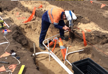
Trenching is a form of excavation in which a large hole is dug; the hole itself is usually quite deep but not very wide, and it is often dug to be long. Trenching is common in construction, especially when installing underground pipes, wires, or structural supports. The practice of trenching is also common in military applications to protect front line troops from gunfire or other hazards. Large trenches can be damaging to a landscape if not properly dug and re-filled after use, and digging trenches is a hazardous job, as the walls of the trench are prone to cave-ins if not properly supported on either side.
A trench digger can be used for trenching, or it may be done by hand with a shovel or pickaxe. Larger trenches are difficult to dig by hand, so a motorized machine has been specially designed to do the job. Trench diggers come in a wide range of sizes to accommodate the digging of many different sizes of trench. Smaller trench diggers are small enough to be operated by one person pushing the digger along the area to be trenched. Larger trench diggers, common in construction settings, are massive machines that must be driven. A large, saw-like arm is lowered to the ground to dig the trench.
Laying of Ducts
Today laying telephone cable underground is still a strenuous job with the methods used surprisingly not changing much from those used in early days.
Originally a channel was dug into the ground along the route of a pre-planned network where a four-inch earthenware pipe would be laid. Depending on the needs of the network, either a wide or thin cable would be pulled through the pipe by rope, leaving some spare space for future use. A large gang of men would have to pull the cable, as it was so heavy.
Spare rope was left in the ducts for future cables, which today are frequently Fibre optic. In fact the only differences now are that the gangs can use machinery to help pull the cables through and if rope is missing or broken, automatic duct motors are used to worm through the pipes threading new lengths.
Blowing of OFC by Compressor in ducts 25,40,50 mm ducts
Optical Fibre cable blowing machine can blow OFC in PLB ducts 40 mm Dia to 50 mm dia at an velocity of 70 meters per minute and machine can accommodate cable size 14 mm dia to 25 mm dia of any configuration either armored or unarmored, machine is run by air drive system powered Ingersoll Rand and machine weighs only 38 kgs. It is very easy to lift from one work point to other point easily, operations of machine is very simple requires only two lever control and can be handled by semi-skilled person. We have sold so many machines in India, Middle East countries, African and Srilanka. Duct Collate size: multi collate sizes for 32mm, 40mm and 50mm in combined pack. The machine also comes with only 40 mm duct collate and 50 mm duct collate.
Splicing by method of fusion splicing
Fusion splicing is the act of joining two optical Fibres end-to-end using heat. The goal is to fuse the two Fibres together in such a way that light passing through the Fibres is not scattered or reflected back by the splice, and so that the splice and the region surrounding it are almost as strong as the virgin Fibre itself. The source of heat is usually an electric arc, but can also be a laser, or a gas flame, or a tungsten filament through which current is passed. Current fusion splicers are either core or cladding alignment. Using one of these methods the two cleaved Fibres are automatically aligned by the fusion splicer [1] in the x, y, z plane, then are fused together. Prior to removing the spliced Fibre from the fusion splicer, a proof-test preformed to ensure that the splice is strong enough to survive handling, packaging and extended use. The bare Fibre area is protected either by recoating or with a splice protector. A splice protector is a heat shrinkable tube with a strength membrane. Optical splicing procedure:
- Characteristics of Place of the splicing process.
- Checking Fibre optic splice closure content and supplementary kits.
- Cable installation in oval outlet
- Cable preparation.
- Organization of the Fibres inside the tray.
- Installing the heat shrinkable sleeve and testing it.
Testing of OFC Network by OTDR
An Optical Time Domain Reflectometer (OTDR) is an important instrument used by organizations to certify the performance of new Fibre optics links and detect problems with existing Fibre links.The health of your network depends on the quality of your network infrastructure. This quality begins with complete certification by contractors or systems integrators that the Fibre cabling infrastructure was properly installed. Maintaining a reliable Fibre plant is also essential in protecting your business-critical applications. As a network administrator, it is important to understand how to get the best performance from your cabling investment and how to solve problems quickly when they occur.Basic Certification sometimes known as Tier 1 Fibre certification is required in all Fibre optic cabling links. The Tier 1 tests are attenuation (insertion loss), length and polarity. When conducting Tier 1 testing, each Fibre link is measured for attenuation and results are documented. This test ensures that the Fibre link exhibits less loss than the maximum allowable loss budget for the immediate application.


